08-05-2024, 05:32 AM
Hi everyone,
I built a 3000 line QB4.5 program in 1988-89 to design specialist modular heat-exchangers. I was a youngish engineer at the time.
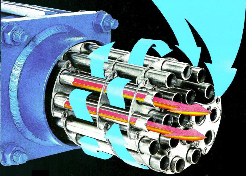
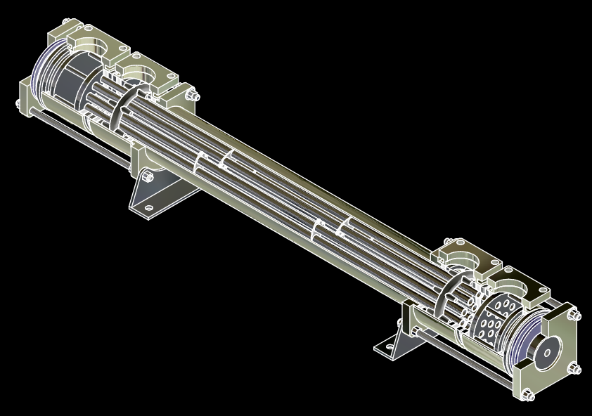
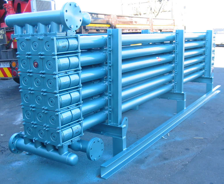
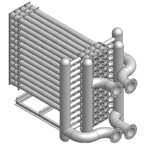
A few links of the MSTHE below, for context:
Link 1
Link 2
Link 3
QB in text mode follows the HE design process very well - the 'inside out' process.
- Primary fluid data - single phase - condensation - evaporation - user input
- Secondary fluid data- single phase - condensation - evaporation - user input
- Heat balance
- Tubeside performance (inside)
- Shellside performance (outside)
- Determine overall module arrangement
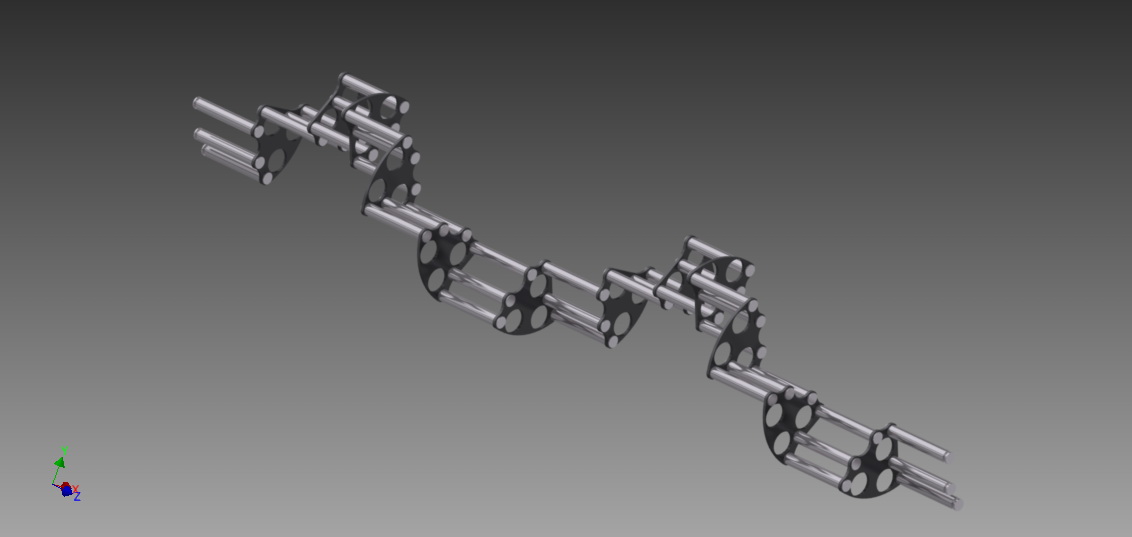
- Spiral cage design
- Printouts
This follows a linear design process and can fork in many different directions at each design point.
QB has followed this design process very well, although the original QB4.5 output was not the prettiest. Recently, I cleaned up the graphics a bit using better screen dimensions and qb64pe's upgraded commands. In Linux I print directly to txt files, then convert directly to pdf files from within the package.
I've always been very loath to jump to another programming language or full graphics display due to the complexity of the design process and its many twists and turns along the design process pathway. So, over the years, I have regularly updated the original code to run on modern computer systems as qb4.5->qb64->qb64pe has developed.
The full story of the technology in modern times can be found on my Patreon and Youtube sites and the following links:
Patreon
Youtube


